Understanding your vehicle’s Data Link Connector (DLC) or diagnostic port is crucial for troubleshooting and maintenance. This guide dives deep into the 1992 Subaru SVX Dlc Pinout, providing a detailed walkthrough of the wiring diagrams to identify the correct connector and its corresponding pin functions.
Locating the DLC
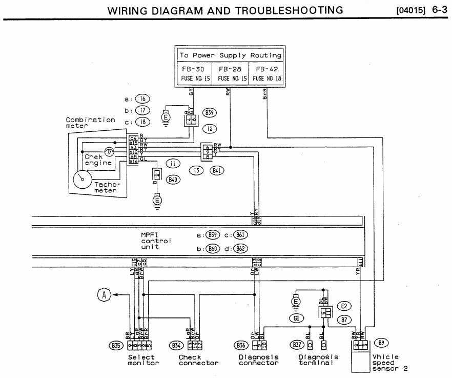
The 1992 Subaru SVX wiring diagram, found in the official service manual, indicates the DLC’s location in the lower left footwell. While the manual doesn’t explicitly label the DLC, referencing “Engine Electrical (MPFI) System” on page 44 (PDF page 43, labeled [0415] 6-3) leads to the relevant diagram:
Further examination of Figure 6 on page 77 (PDF page 11, labeled [0500] 6-3) helps narrow down the possibilities:
This diagram allows us to eliminate the B37 Diagnosis Terminal and the B36 Diagnosis Connector as potential DLC candidates.
Identifying the Correct Connector
Page 82 (PDF page 91, labeled [0604] 6-3) showcases all connectors within the lower left footwell (Figure 69):
Along with connector images, we have their corresponding names:
Based on these images and prior exclusions, B58 (airbag system) and B33 (temperature unit setting) are also ruled out. This leaves us with B34 and B35 as the remaining contenders.
Analyzing B34 and B35
Knowing that this generation Subaru typically uses a 12-pin DLC, we can analyze the pin count of B34 and B35. While B34 has 9 pins and B35 has 20, both utilize fewer pins for ECU connection.
Referring back to page 42 reveals the pinouts for each connector:
Page 2 (PDF page [0102] 6-3) provides a guide on interpreting these diagrams (Figure 2):
Furthermore, the color code diagram on page 4 (PDF page [0102] 6-3) is essential for understanding the wiring:
Pinout Breakdown
B34:
- Pin 13 (Light Green/Red) connects to
B61 Pin 7 - Pin 14 (Brown/White) connects to
B61 Pin 8 - Pin 17 (Orange) connects to
B61 Pin 13
B35:
- Pin 9 (Black/Red) connects to
(A)– Note: Destination “(A)” requires further investigation within the wiring diagram. - Pin 8 (Blue/Yellow) connects to
B61 Pin 15 - Pin 3 (Light Green/Red) connects to
B61 Pin 7 - Pin 2 (Brown/White) connects to
B61 Pin 8 - Pin 5 (Brown/Red) connects to
FB-42 Fuse No. 18
Conclusion
While this analysis provides a strong foundation for understanding the 1992 Subaru SVX DLC pinout, further investigation is necessary to definitively identify the correct connector (B34 or B35) as the DLC. Consult the complete wiring diagram and verify the connections to pinpoint the DLC and its specific pin functions. This information will enable accurate diagnostics and troubleshooting using appropriate OBD equipment.

