The GM coolant temperature sensor, part #12146312, is a common component used to monitor engine temperature. This article provides a comprehensive guide to understanding its functionality and integrating it with an Arduino for custom temperature monitoring applications. We’ll cover the sensor’s specifications, wiring diagram, and provide a working Arduino code example.
Decoding the GM Coolant Sensor (Part #12146312)
The GM Coolant Sensor (#12146312) is a two-wire thermistor that changes resistance based on the temperature of the coolant. It’s a critical component for engine management, providing data to the vehicle’s computer to adjust fuel injection and other parameters. This sensor mounts using a standard 3/8″ pipe thread and utilizes a two-wire connector. You can find the official datasheet with connector specifications here: DELPHI COOLANT TEMPERATURE SENSOR PART NUMBER 12146312.
Wiring the Coolant Sensor to Arduino
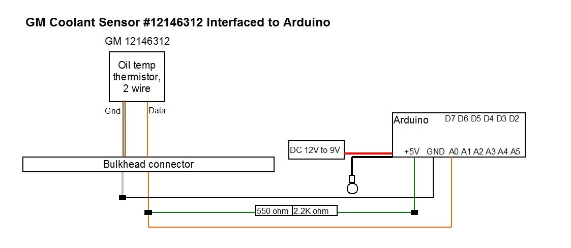
Connecting the coolant sensor to an Arduino requires a voltage divider circuit to convert the varying resistance into a readable voltage signal. The sensor expects a 5V supply from the vehicle’s computer. For Arduino integration:
- Ground Connection: Connect the sensor’s ground wire to the Arduino’s ground pin.
- Signal Connection: Connect the sensor’s signal wire to a voltage divider circuit. This circuit consists of a 2.2K ohm resistor and a 550 ohm resistor connected in series. Connect one end of the series resistors to the sensor’s signal wire, and the other end to the Arduino’s 5V pin. The junction between the two resistors is connected to the Arduino’s analog input pin (e.g., A0). This configuration allows the Arduino to measure the voltage drop across the 550 ohm resistor, which varies with the sensor’s resistance and therefore, the temperature.
 GM_12146312 wiring diagram
Arduino Code for Reading the Coolant Sensor
The following Arduino code reads the analog voltage from the sensor, converts it to a temperature reading using the Steinhart-Hart equation, and prints the temperature in Fahrenheit to the serial monitor. You can modify the code to display the temperature in Celsius or use it to control other components based on the temperature reading.
// Code for reading GM coolant sensor (Part #12146312) with Arduino
// Sensor requires a 2.2K and 550 ohm resistor voltage divider
// Output is in Fahrenheit (modify for Celsius)
// Uses analog pin A0

#include <math.h>

void setup() {
  Serial.begin(115200); // Set baud rate for serial communication
}

double Thermister(int RawADC) {
  // Steinhart-Hart equation for temperature calculation
  double Temp;
  Temp = log(((10240000/RawADC) - 10000));
  Temp = 1 / (0.001129148 + (0.000234125 + (0.0000000876741 * Temp * Temp ))* Temp );
  Temp = Temp - 273.15;    // Convert Kelvin to Celsius
  Temp = (Temp * 9.0)/ 5.0 + 32.0; // Celsius to Fahrenheit
  return Temp;
}

void loop() {
  int val;              // Variable to store analog reading
  double temp;           // Variable to store temperature value

  val = analogRead(0);    // Read analog value from pin A0
  temp = Thermister(val); // Calculate temperature using Steinhart-Hart equation

  Serial.print("Coolant Temperature: ");
  Serial.println(temp);   // Print temperature to serial monitor

  delay(1000);           // Delay for 1 second
}
Conclusion
This guide provides a practical approach to utilizing a GM coolant sensor with Arduino. By understanding the sensor’s characteristics and implementing the provided wiring and code, you can accurately monitor coolant temperature for various applications. Remember to adjust the code and wiring according to your specific needs.

