
A control relay is a fundamental component in many electrical systems, acting as an electrically controlled switch to manage high-power circuits. Understanding the wiring diagram of a control relay is crucial for proper installation and operation. This article delves into the intricacies of 4-pin and 5-pin Control Relay Wiring Diagrams, providing a comprehensive guide to their functionality and applications.
What is a Control Relay and Why is it Important?
Control relays utilize a small current to control a much larger one, enabling safe and efficient management of high-power devices like motors, lights, and valves. By energizing a coil within the relay, a magnetic field is generated, causing a set of contacts to open or close, thereby controlling the flow of electricity in the connected circuit. This allows for remote operation, automation, and the implementation of safety mechanisms in complex systems.
Decoding the 4-Pin Control Relay Wiring Diagram
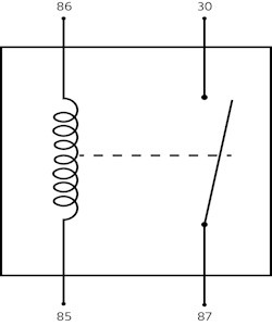
4-pin relays are designed for simple on/off switching of a single circuit. Two pins (85 and 86) control the relay coil, while the remaining two (30 and 87) manage the switching action. There are two primary types:
- Normally Open (NO): In the default state, the contact is open. When the coil is energized, the contact closes, completing the circuit.
- Normally Closed (NC): The contact is closed in its resting state. Energizing the coil opens the contact, interrupting the circuit.
When power is applied to pins 85 and 86, the coil activates, creating a magnetic field. This field either closes the NO contact or opens the NC contact, depending on the relay type.
Understanding the 5-Pin Control Relay Wiring Diagram
5-pin relays offer more complex switching capabilities, allowing for control over two separate circuits. They utilize pins 85 and 86 for the coil, while pins 30, 87, and 87A manage the switching between two circuits.
In a 5-pin relay, one contact is normally closed (87A) and the other normally open (87). Energizing the coil switches the connection from 87A to 87, effectively transferring power from one circuit to another.
Protecting Your Relay Circuit: Essential Considerations
Switching off a relay can generate a voltage spike that might damage sensitive electronic components. To mitigate this risk, protective devices like diodes or resistors are often incorporated into the circuit to suppress these voltage surges.
Practical Application: Control Relay Wiring Diagram Example
A common application is using a 4-pin relay to control high-current automotive lighting. A low-current switch activates the relay, which in turn switches the high-current flow to the headlights. This protects the switch from damage and ensures efficient power delivery.
Control and Relay Panels: Centralized Control Systems
Control and Relay Panels (CRPs) house multiple relays, along with other components like circuit breakers, fuses, and meters, to provide centralized control and monitoring of complex electrical systems in industrial and commercial settings.
Key Differences: 4-Pin vs. 5-Pin and Relay vs. Communicating Controls
- 4-Pin vs. 5-Pin: 4-pin relays control one circuit, while 5-pin relays manage two, enabling switching between them.
- Relay vs. Communicating Controls: Traditional relay controls handle basic on/off functions. Communicating controls utilize digital communication for advanced automation and data exchange.
Conclusion
Understanding control relay wiring diagrams is paramount for anyone working with electrical systems. Whether dealing with a simple 4-pin relay or a more complex 5-pin configuration, grasping the principles of operation and the importance of protective measures will ensure safe and efficient circuit control. This knowledge is fundamental for a wide range of applications, from automotive systems to industrial automation.