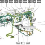
The 5.9 Cummins engine, renowned for its power and durability, relies heavily on its Engine Control Module (ECM) for optimal performance. Understanding the 5.9 Cummins Ecm Wiring Diagram is crucial for diagnosing and troubleshooting electrical issues. This guide provides a detailed overview of the wiring diagram, covering both the C1 and C2 connectors.
Understanding the 5.9 Cummins ECM Wiring Diagram
The ECM, often referred to as the “brain” of the engine, manages various functions, including fuel injection, timing, and emissions control. The wiring diagram acts as a roadmap, illustrating the connections between the ECM and various sensors, actuators, and relays throughout the engine. A thorough understanding of this diagram is essential for any mechanic or enthusiast working on a 5.9 Cummins.
Module-Engine Control C1 – 60 Way Connector
The C1 connector on the 5.9 Cummins ECM houses 60 circuits, each responsible for a specific function. Key circuits include:
- Pin 1: K139 – Wastegate Solenoid Control
- Pin 4: D72 – CCD Bus (+)
- Pin 5: D71 – CCD Bus (-)
- Pin 6: K65 – Fuel Pump Relay Return
- Pin 7: K20 – Generator Field Control
- Pin 11: K2 – ECT (Engine Coolant Temperature) Signal
- Pin 12: K181 – Fuel Rail Sensor Signal
- Pin 15: K21 – Intake Air Temperature Sensor Signal
- Pin 18: K23 – APPS (Accelerator Pedal Position Sensor) No. 1 Signal
- Pin 19: K31 – Fuel Pump Relay Control
This image illustrates a section of the C1 connector with pin designations and corresponding wire colors. Referencing a complete wiring diagram is crucial for accurate identification.
This list represents only a fraction of the circuits within the C1 connector. Consulting a comprehensive 5.9 Cummins wiring diagram is vital for detailed information.
Module-Engine Control C2 – 50 Way Connector
The C2 connector, with 50 circuits, manages another set of crucial engine functions. Some important circuits include:
- Pin 3: K615 – Inlet Air Temperature Sensor
- Pin 5: K176 – Intake Air Heater No. 2 Relay Control
- Pin 6: K174 – Intake Air Heater No. 1 Relay Control
- Pin 7: K31 – Fuel Pump Relay Control
- Pin 9: T41 – Park/Neutral Position Switch Sense (Automatic Transmission)
- Pin 10: K161 – Fan Speed Sensor
- Pin 11: B22 – Vehicle Speed Signal No. 1
- Pin 12: G6 – Oil Pressure Signal
- Pin 26: N4 – Fuel Level Sensor Signal
This image shows a portion of the C2 connector. Note the different wire colors and pin assignments compared to the C1 connector. Always refer to a complete diagram for accurate information. Using the wrong information can lead to misdiagnosis and potential damage.
Utilizing the Wiring Diagram for Troubleshooting
The 5.9 Cummins ECM wiring diagram is invaluable for diagnosing electrical problems. By tracing circuits and checking for continuity, voltage, and resistance, you can pinpoint faulty components like sensors, actuators, or wiring harnesses.
Conclusion
The 5.9 Cummins ECM wiring diagram is an indispensable tool for anyone working on this powerful engine. This guide provides a foundational understanding of the diagram’s importance and complexity. However, always consult a complete and year-specific wiring diagram for your particular 5.9 Cummins engine before undertaking any diagnostic or repair work. A comprehensive understanding of this diagram is crucial for accurate troubleshooting and maintaining the optimal performance of your engine.

